Building Beaver Lake
Online Exhibit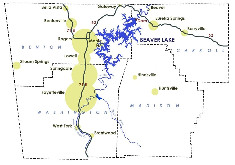 What would Northwest Arkansas be like without Beaver Lake? Would we be as economically prosperous? Would we be able to support a large population? Would as many tourists visit? Probably not. The landscape and community of Northwest Arkansas changed with the coming of Beaver Lake.
Today many of us think of Beaver Lake as a water source and as a place to enjoy recreational activities, but its original purpose was for power generation and flood control. Tremendous floods in the 1920s and 1930s prompted Congress and the U.S. Army Corps of Engineers to take action against future disasters. Many areas across the nation were recommended for improvement, including the White River Basin. And so began the struggle to secure the authority—and the funds—to build a series of reservoirs along the White River and its tributaries.
The White was a strong, clear river, home to big catfish and lined with huge walnut and cherry trees. Native Americans first benefited from the river, and later homesteaders settled along its banks, raising families, farming land, and operating businesses among the forested hills, limestone bluffs, and deep valleys. Much of this land came to be covered by the waters of Beaver Lake.
The lake’s name comes from the town of Beaver in Carroll County, originally homesteaded by Wilson Beaver. At first the dam was to be built near Beaver, until it was determined that the area’s geography and geology weren’t suitable. Instead the dam was built six miles northwest of nearby Eureka Springs.
The Beaver Lake project cost over $43 million. The money was used to purchase property, relocate cemeteries, roads, and utility lines, clear the reservoir area, build the dam, powerhouse, and auxiliary embankment dams, and engineer and supervise the entire project. The contract for the dam was awarded to the T.L. James & Co. of Ruston, Louisiana, and the J.A. Jones Construction Co. of Charlotte, North Carolina, which together submitted a bid of $15.9 million.
The Corps of Engineers operates the five reservoirs that make up the integrated water resource system in the White River Basin: Beaver, Table Rock (in Missouri), and Bull Shoals (near Mountain Home) on the White River; Norfork on the North Fork River; and Greers Ferry (near Heber Springs) on the Little Red River.
The original purpose of the reservoir was for flood control and power generation. It was only later, around the time that the lake was built, that the lake’s use as a municipal and industrial water supply and as a recreational resource began to take shape. The lake was one of the first in the nation to include these benefits as part of its mandated purpose.
Many of the images in this exhibit were donated by Thomas E. Petermann, project engineer in charge of building Beaver Dam and powerhouse. He also wrote a synopsis of the project that serves as an invaluable resource for historians.
To learn more about the big picture that Beaver Lake is a part of, take a look at these resources:
What would Northwest Arkansas be like without Beaver Lake? Would we be as economically prosperous? Would we be able to support a large population? Would as many tourists visit? Probably not. The landscape and community of Northwest Arkansas changed with the coming of Beaver Lake.
Today many of us think of Beaver Lake as a water source and as a place to enjoy recreational activities, but its original purpose was for power generation and flood control. Tremendous floods in the 1920s and 1930s prompted Congress and the U.S. Army Corps of Engineers to take action against future disasters. Many areas across the nation were recommended for improvement, including the White River Basin. And so began the struggle to secure the authority—and the funds—to build a series of reservoirs along the White River and its tributaries.
The White was a strong, clear river, home to big catfish and lined with huge walnut and cherry trees. Native Americans first benefited from the river, and later homesteaders settled along its banks, raising families, farming land, and operating businesses among the forested hills, limestone bluffs, and deep valleys. Much of this land came to be covered by the waters of Beaver Lake.
The lake’s name comes from the town of Beaver in Carroll County, originally homesteaded by Wilson Beaver. At first the dam was to be built near Beaver, until it was determined that the area’s geography and geology weren’t suitable. Instead the dam was built six miles northwest of nearby Eureka Springs.
The Beaver Lake project cost over $43 million. The money was used to purchase property, relocate cemeteries, roads, and utility lines, clear the reservoir area, build the dam, powerhouse, and auxiliary embankment dams, and engineer and supervise the entire project. The contract for the dam was awarded to the T.L. James & Co. of Ruston, Louisiana, and the J.A. Jones Construction Co. of Charlotte, North Carolina, which together submitted a bid of $15.9 million.
The Corps of Engineers operates the five reservoirs that make up the integrated water resource system in the White River Basin: Beaver, Table Rock (in Missouri), and Bull Shoals (near Mountain Home) on the White River; Norfork on the North Fork River; and Greers Ferry (near Heber Springs) on the Little Red River.
The original purpose of the reservoir was for flood control and power generation. It was only later, around the time that the lake was built, that the lake’s use as a municipal and industrial water supply and as a recreational resource began to take shape. The lake was one of the first in the nation to include these benefits as part of its mandated purpose.
Many of the images in this exhibit were donated by Thomas E. Petermann, project engineer in charge of building Beaver Dam and powerhouse. He also wrote a synopsis of the project that serves as an invaluable resource for historians.
To learn more about the big picture that Beaver Lake is a part of, take a look at these resources:
Timeline
1927. Great Flood devastates six southern states, including Arkansas
1929. Corps begins flood-control study of White River Basin
1937. More flooding causes Congress to approve national flood-control plan
1938. Passage of Flood Control Act authorizing Corps to build six flood-control lakes in White River Basin
1941. Passage of Flood Control Act authorizing Norfolk and Bull Shoals Dams
1944. Passage of Flood Control Act allows Southwest Power Administration to market power generated by lakes
1949. Beaver Dam Association incorporates
1954. Passage of Flood Control Act authorizing addition of Beaver Lake for flood control and power generation to White River plan
1957. Beaver Water District incorporates
1958. Passage of Water Supply Act approving municipal and industrial water storage in federally constructed reservoirs
1959. Corps completes first land purchase
1960. Construction begins on dam; Beaver Water District contracts for water rights
1963. Construction begins on powerhouse and switchyard
1964. Dam complete and water impoundment begins
1965. Passage of Recreational Act allows for federally constructed reservoirs to include recreation as a project purpose; power generation begins
1966. Beaver Lake complete; Beaver Water District goes on line; Northwest Arkansas Regional Planning Committee incorporates to strategize for growth in Beaver Lake area
Fun Facts
Amount of Arkansas underwater during 1927 flood: 6,600 square miles
Number of counties affected: 36 of 75
Percentage of Arkansans who get their drinking water from the lake: 14% (over 420,000 people)
Number of cemeteries relocated: 39
Number of graves moved: 1,584
Amount of water Beaver Water District can produce daily (as of 2014): 140 million gallons
Length of White River affected by project: 70 miles
Number of visits in 2016 to Corps of Engineer-run parks at Beaver Lake: over 2.6 million
Amount of cement used: 600,000 barrels
Height of mixing plant: 120 feet
Height of crane operator above trestle: 80 feet
Length of trestle: 1,150 feet
Size of aggregate: 6 inch, 3 inch, 1½ inch, ¾ inch
Distance apart of gantry rails: 32 feet
Weight of four-cubic-yard bucket of concrete: 11 tons
Amount of concrete produced per hour: 150 cubic yards
Estimated cost of project: $51 million
Actual cost of project: $43 million
Dimension of lift: 48-feet wide by 7½-feet high
Amount of concrete used in dam: 133,000 truck loads
Number of monoliths: 28
Height of dam: 228 feet
Amount of concrete in dam: 780,000 cubic yards
Length of concrete dam: 1,333 feet
Width of dam at base: 180 feet
Width of dam at top: 32 feet
Capacity of water storage tanks: 16,000 gallons
Length of cooling conveyor: 350 feet
Length of embankment: 1,242 feet
Amount of rock and soil in embankment: 1.7 million cubic yards
Amount of water in one acre-foot: 325,850 gallons
Dimensions of each gate: 40 feet wide by 37 feet high
Length of spillway: 328 feet
Bid for construction of powerhouse: $3.7 million
Diameter of penstock: 20½ feet
Capacity of each turbine: 77,400 horsepower (about 553 average-sized cars)
Dimensions of sluice gate: 6 feet by 10 feet
Amount of time to go from zero-power generation to full load: 3 minutes
Length of shoreline: 450 miles
Number of people projected to be living in area by 2055: 1.2 million
Photo Gallery
Before the Lake, A River
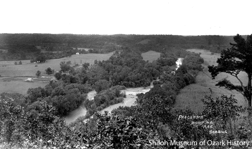
The White River as seen from Panorama Point near Monte Ne, circa 1920. W.B. Grabill Collection (S-86-210-4)
The White River starts near Fayetteville and flows north into Missouri before returning to Arkansas. In 1926 and 1927 heavy rains throughout the Midwest and South dumped an enormous amount of water into the White and other rivers that flow into the Mississippi River. The Great Flood of 1927 began on April 16 when a levee broke in Illinois. As the water flowed downstream, more levees broke.
The floodwaters devastated the South. Over 27,000 square miles of land were flooded in Illinois, Kentucky, Tennessee, Mississippi, Louisiana, and Arkansas. Nearly 1,000 people lost their lives, one million people were displaced, and 130,000 homes were destroyed.
It was because of this flood that the Federal government began looking into ways to manage the nation’s rivers. In 1929 the U.S. Army Corps of Engineers began a $61,000 flood-control study of the White River Basin, concluding that a series of dams was needed.
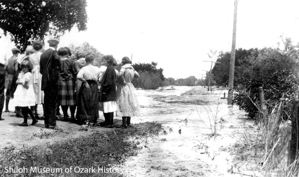
Residents watch the flooding of the West Fork of the White River, near Brentwood (Washington County), April 15, 1927. Bertha Cartmell Reid and George Cartmell Collection (S-89-105-241)
The Vision
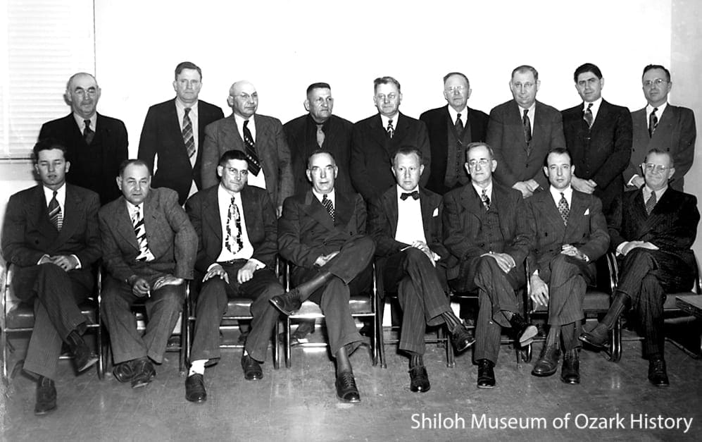
Members of the Beaver Dam Association, circa 1950. Front row, from left: Willis Shaw (Elm Springs), Claud Morsani (Tontitown), vice-president Joe Robinson (Springdale), president Earl Harris (Rogers), secretary-treasurer Courtney Crouch (Springdale), Mace Howell (Springdale), Paul Young (Fayetteville), unidentified. Back row, from left: Elbert Graham (Lowell), State Senator Russell Elrod (Siloam Springs), J. J. Neil (Springdale), Albert Price (Eureka Springs), unidentified, unidentified, Shelby Ford (Springdale), Carl Shores (Cave Springs), unidentified. Springdale Chamber of Commerce Collection (S-77-9-294)
Northwest Arkansas lobbied for the construction of Beaver Lake. In 1949 area leaders formed the Beaver Dam Association to study such things as erosion and flooding on the upper White River and to look into irrigation, municipal water, and hydroelectric power, all in order to promote the lake’s construction.
The Beaver Water District was formed in 1957 by the cities of Bentonville, Fayetteville, Rogers, and Springdale to secure a long-term supply of water for Benton and Washington Counties. The District paid for five additional feet of dam height for water storage.
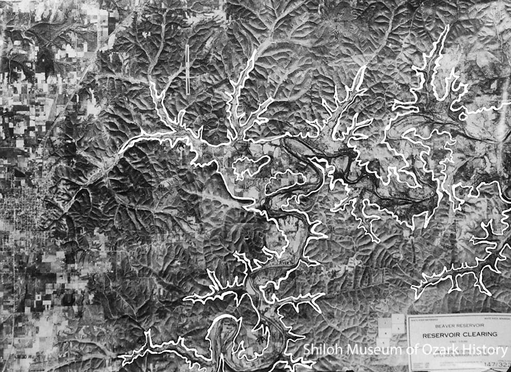
One of five aerial maps produced by the Corps of Engineers illustrating the area to be cleared for the reservoir, July 1960. The future footprint of the lake is marked in white. Rogers is on the left. Joe Neal Collection (S-89-14)
The Corps of Engineers had to purchase over 40,000 acres of land to make way for the reservoir. It was a difficult task because land titles back in the hills were informal or non-existent and owners or their heirs were scattered.
Because the White was a meandering river, the lake took on an irregular shape as the impounded waters backed up into the hills and valleys of the river basin.
Not only did the lake change the geographical landscape of the area, it changed the historical and cultural landscapes. Families whose ancestors homesteaded along the White were forced to move their homes and cemeteries as the lake rose to cover farms, small towns and communities, Native American archeological sites, and historical sites such as the resort at Monte Ne.
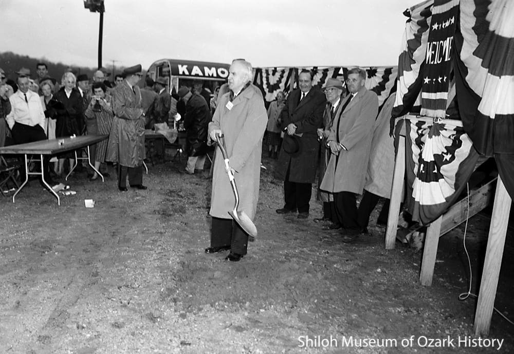
U. S. Representative James W. Trimble at the groundbreaking for Beaver Dam, November 22, 1960. The men to his right are, from left: Governor Orval E. Faubus, Clarence Byrnes, and Joe Robinson, president of the Beaver Dam Association. Springdale News Collection (SMN pre-65-23)
It was fitting that U.S. Representative James W. Trimble of Berryville was the first to break earth at the dam site, because he was a leading advocate for Beaver Lake. Although there was opposition to the reservoir in Congress, by adding water supply to the reservoir’s purpose he was able to secure the necessary funds in 1954. At the ceremony Trimble envisioned a day when “…family groups with children will enjoy outings on the shores of the emerald lake to be created here, when young lovers will make plans for a brighter future, and older folks will look in increasing numbers to our beautiful Ozarks as an ideal place for retirement in their golden years.”
Governor Faubus declared, “Nature has given to the Ozarks their unmatched beauty. Now Beaver Dam will help this hill country grow into one of the most prosperous areas of our nation.”
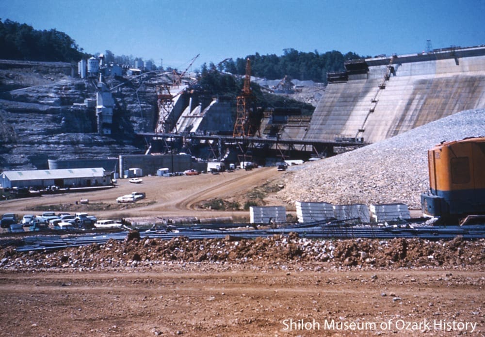
Prepping the Dam Site
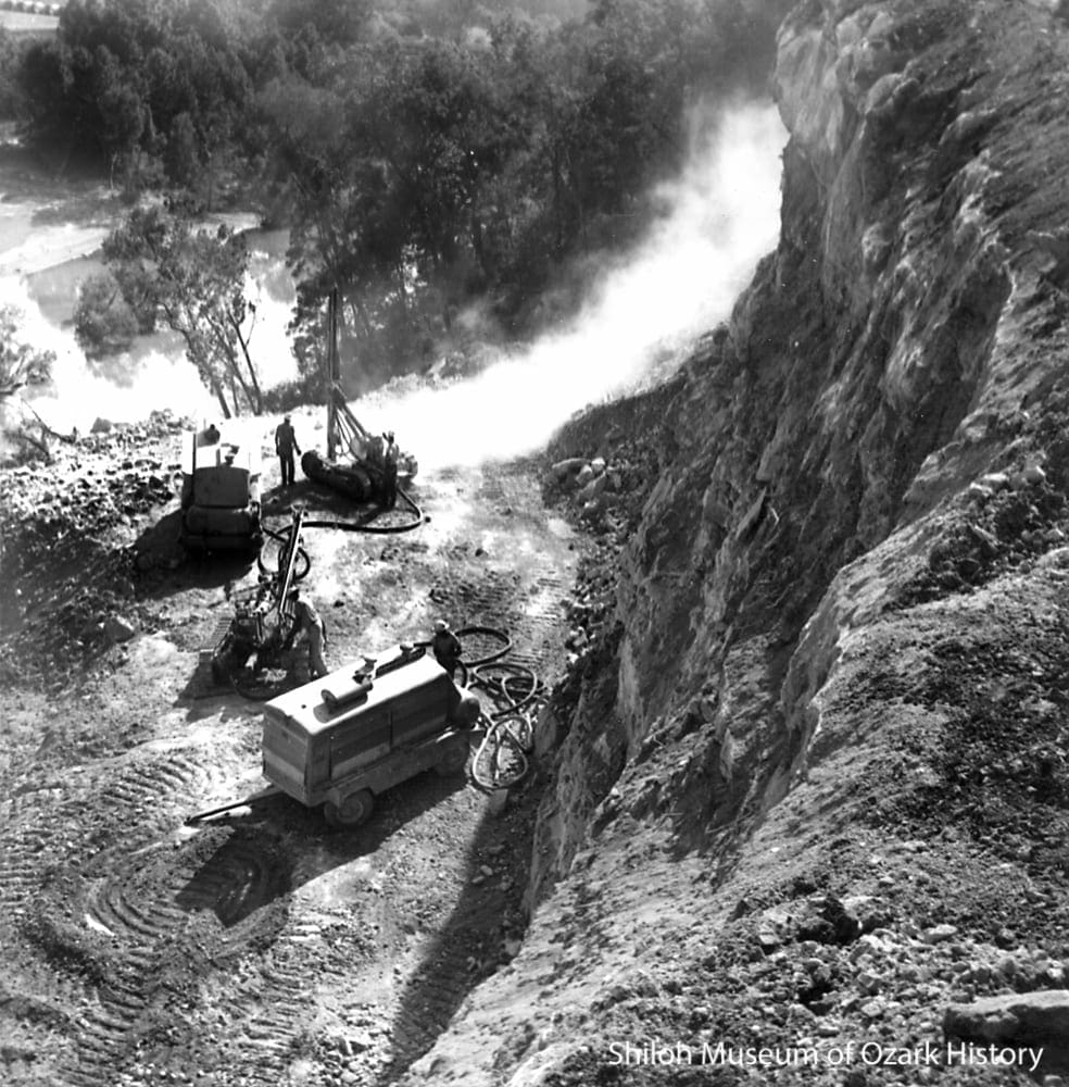
Preparing a bluff ledge for the concrete mixing plant, early 1961.
Thomas E. Petermann Collection (S-2005-89-53)
The best site for the dam was found about six miles northwest of Eureka Springs, where the White River flowed past a 350-feet-tall bluff on one side and a more gradual rise of 250 feet on the other.
To bring machinery and supplies to the dam site, the Frisco Railroad built a 20-car spur near Gateway on the Arkansas-Missouri border. Materials traveled down Highway 62 and then onto a newly built three-mile-long access road.
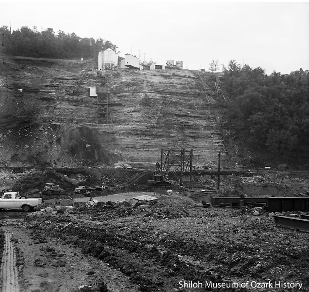
Bluff with the trestle and mixing plant under construction, June 1961. Thomas E. Petermann Collection (S-2005-89-67B)
The contract to build the dam was awarded on November 16, 1960. For the next four years tremors, noise, dust, and diesel fumes filled the sleepy little valley.
Two electric whirley cranes were used to build the dam. Each crane revolved 360 degrees on its base, allowing the operator to move heavy construction materials and concrete in all directions. The cranes were mounted on 75-feet-tall gantries, movable steel towers perched atop a steel trestle (bridge) spanning the length of the dam.
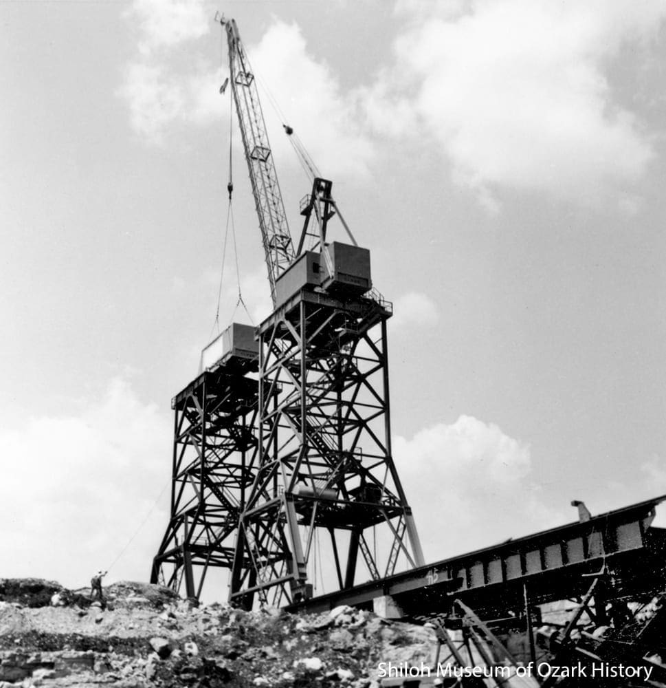
A whirley crane places a second crane, June 1961. Thomas E. Petermann Collection (S-2005-89-57)
Care had to be taken to keep the crane from overextending and toppling over. The heavier the load hanging from the end of the long boom, the closer it needed to stay to the center of the crane.
A used mixing plant was purchased from the Niagara Falls Power Project in New York in 1960. It was taken apart and shipped by rail to Gateway.

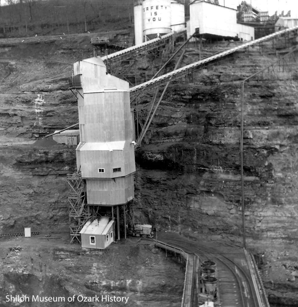
The concrete mixing plant (front) and the trestle for the whirley cranes (back) under construction, August 1961. The White River flows below the concrete plant. Thomas E. Petermann Collection (S-2005-89-62)
Cement and aggregate (crushed stone) were stored in the plant above a structure which sorted the aggregate into various sizes. From there the materials went into batching hoppers to be measured and weighed and then into one of four mixers, each capable of holding four cubic yards of concrete.
Along with the tracks for the whirley crane gantries, two sets of railroad tracks were installed on the trestle, allowing for the coming and going of the flatcars hauling giant buckets of concrete.
Rock Crushers and Concrete

Part of the rock-crushing plant, December 1961. Thomas E. Petermann Collection (S-2005-89-100)
Concrete is made of aggregate, sand, water, Portland cement, and sometimes flyash, a filler material that is a by-product of coal-burning plants. To keep costs down, the aggregate quarry was located at the top of the bluff.
The concrete mixing plant, December 1961. A railroad flatcar with buckets of concrete is seen in front. Thomas E. Petermann Collection (S-2005-89-105)
Rock was blasted to a depth of 90 feet and hauled to the rock-crushing plant near the bluff’s edge. After it was crushed and screened into various sizes, the rock was stored in recovery tunnels and moved by conveyor belt to the mixing plant.
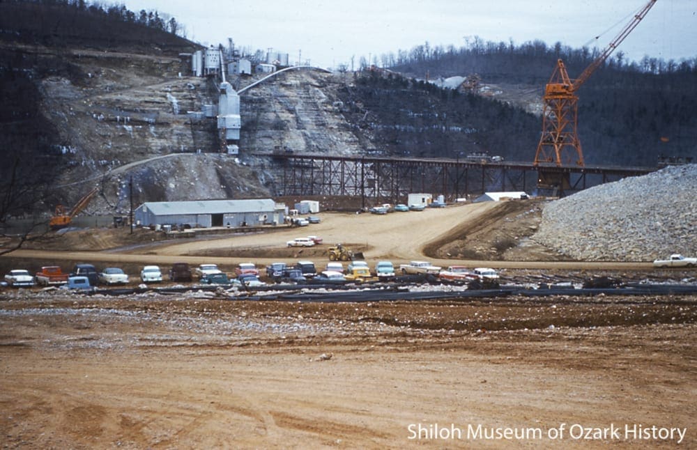
The finished trestle, January 1962. Bettye Mohney Collection (S-86-124-38:3)
The project was a joint venture between the T. L. James and J. A. Jones construction companies. As contractor they oversaw all phases of the work including scheduling and delivery of supplies and equipment, securing electrical power to the site, and letting out subcontracts for preparing the foundation and operating the quarry. The contractor also hired the work crew. Some were seasoned professionals who traveled from project to project, but most were local workers.
The contractor built warehouses, fueling depots, equipment maintenance sheds, project offices, temporary roads and a bridge across the river, a carpentry shop, an inspection building, parking areas, lay-down areas for materials and equipment, and an electrical substation. In the end, the dam and powerhouse were completed ahead of schedule and under budget
Monoliths on the Rise

Whirley cranes moving buckets of concrete to a monolith, December 1961. Thomas E. Petermann Collection (S-2005-89-104)
A gravity dam is made up of monoliths, giant concrete blocks built on top of and next to each other. To create the monoliths, cantilevered steel lifts (forms) are used to hold and shape the concrete until it is hardened. Chilled concrete, shallow lifts, and a precisely calculated cure time prevent the concrete from cracking.
After steel reinforcing rods were put into position, concrete was poured onto the sandblasted surface of the hardened monolith below the lift. The concrete mix was so stiff when it was poured that workers were able to walk on it and use a six-inch vibrator to consolidate the concrete and remove air pockets.
The worksite behind an earthen cofferdam, December 1961. Thomas E. Petermann Collection (S-2005-89-101)
Three cofferdams made of earth or steel sheet piling were erected at different stages of the project. They served as temporary barriers to keep the White River from flooding the worksite.
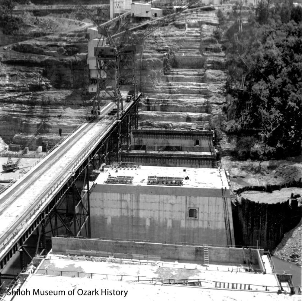
Monoliths under construction, December 1961. Thomas E. Petermann Collection (S-2005-89-98)
Beaver Dam is not made of solid concrete. Tunnel-like access galleries run along the length of the dam. To make an opening in the concrete, a wood-and-plywood form was built and positioned inside the monolith. The concrete was poured around the form and once hardened, the form was removed.
Equipment is housed in the operator’s gallery. Below it is the lower gallery which follows the bottom of the dam. To prevent water seepage, the foundation rock is pressure-grouted through holes in the gallery floor. Any seepage that does occur flows down drain holes to a sump pump. To monitor tilt in the dam caused by the water pressure of the reservoir, a tilt meter (a large plumb bob) hangs in a vertical gallery and measurements are taken quarterly.
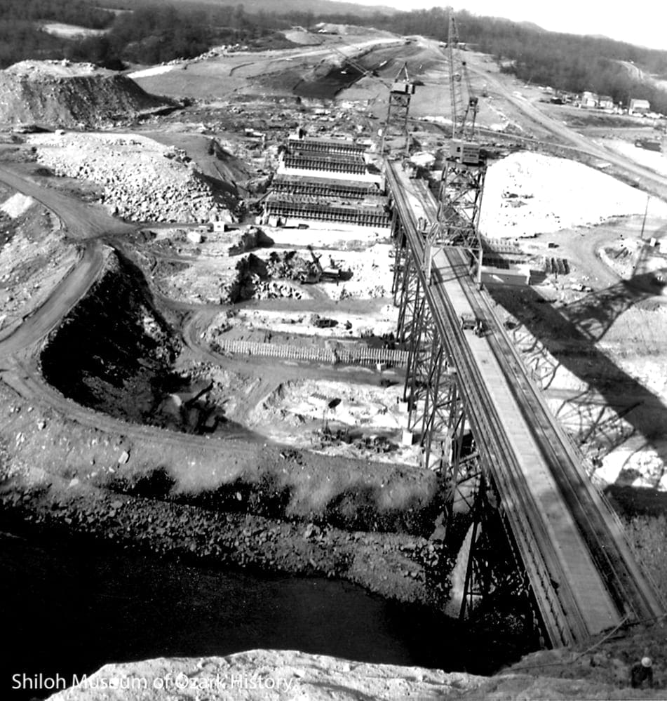
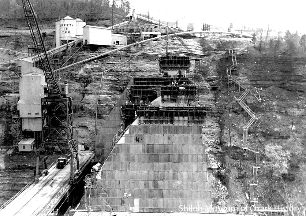
Monoliths on the rise, July 1962. Bettye Mohney Collection (S-86-124-38:7)
A number of problems had to be overcome at the dam site. To transport heavy Portland cement to the mixing plant, a temporary bridge across the White River and a road to the high bluff were built.
To make best use of the quarry atop the bluff, the concrete mixing plant was placed on a ledge halfway down the bluff face. The height of the plant determined the height of the trestle and the whirley cranes. But the cranes couldn’t reach the part of the dam next to the bluff, so a stationary stiff-leg derrick was mounted on the dam.
Because the first monoliths were constructed opposite the bluff, the entire trestle had to be completed to move the concrete from the mixing plant to the worksite. This meant that some of the trestle footings had to stand in the flowing river. Holes were drilled into the bedrock and reinforced concrete footings installed.
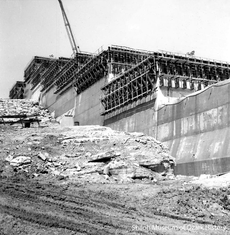
The southern monoliths under construction, July 1962. Thomas E. Petermann Collection (S-2005-89-113)
Beaver Dam is a concrete gravity dam. It uses its massive weight to hold back the water in the reservoir. Roughly triangular in shape, the dam has a wide base which counteracts the enormous horizontal water pressure found at the bottom of the lake. At the top of the triangle, where there is little water pressure, the dam is narrow.
In order to anchor the dam to the limestone bluff, deep notches or keyways were blasted into the rock face. The leftover rock was used to build the earthen embankment anchoring the other side of the dam, opposite the bluff.
The Spillway and the Powerhouse
Slip forms used to construct the narrow, arched walls of the spillway, April 1963. Below the gantry the dinkey locomotive hauls a flatcar of concrete. Thomas E. Petermann Collection (S-2005-89-117)
When water is added to the dry ingredients that make up concrete, it causes it to harden, releasing heat which can make the concrete crack. To prevent this at Beaver Dam, concrete was poured at a temperature of 50 degrees Fahrenheit or less.
On the bluff above the mixing plant were several operations designed to keep the concrete and its ingredients cool. A 1,200-ton refrigeration plant made chilled water to mix into the concrete. Chilled water was also sprayed onto the crushed rock as it moved along the conveyor, and then the water was vibrated out before it went into the mixing plant. To cool the coarse aggregate in the storage bins, cold air was forced through it.
Ammonia refrigeration plants made flaked ice, which was stored in an insulated storage house. The ice was moved along a screw conveyor into the ice batcher in the mixing plant. During hot weather more ice than water was added to the concrete mixture to keep it cool.
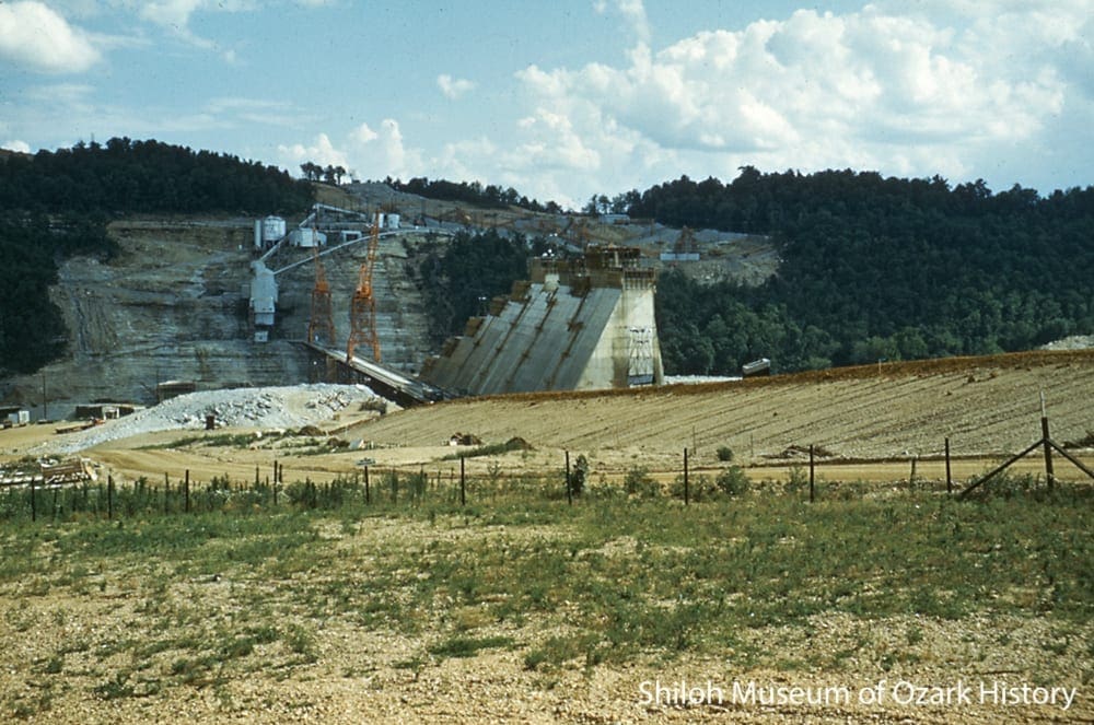
The spillway under construction, June 1963. Part of the embankment is seen at right. Bettye Mohney Collection (S-86-124-38:13)
An earthen embankment spans the gap between the concrete dam and the sloping countryside around it. To build the embankment a keyway was blasted into the bedrock. Then a cutoff wall made of impervious (non-porous) clay was built to resist water seepage from the lake. Pervious (porous) rock from White River gravel bars was piled against the clay core to equalize water pressure.
Rock-and-earth fill material forms the massive sloping sides of the embankment. Fill came from the dam excavation itself and from several nearby pits, some of which contained human graves that first had to be relocated by the Corps of Engineers before the fill could be removed. Riprap (large rocks) was placed on top of the embankment’s slopes to control erosion.
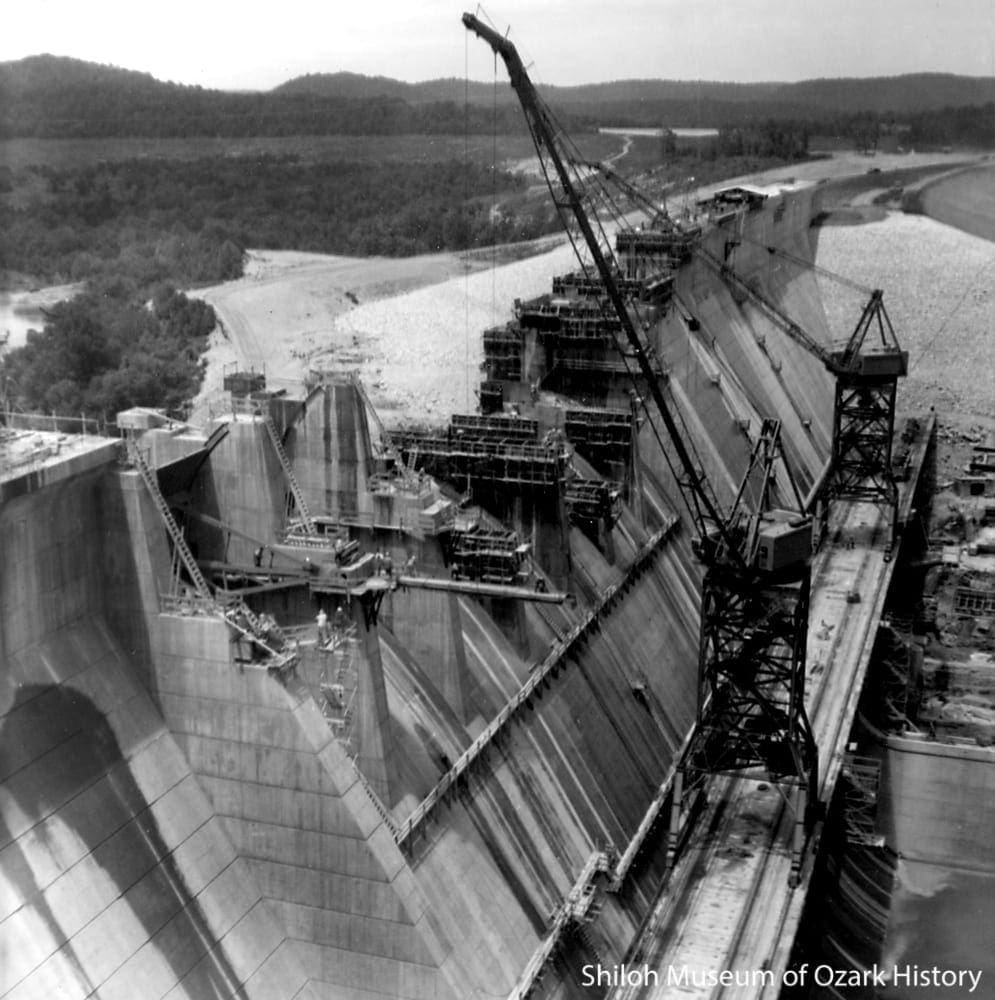
The spillway under construction, April 1963. The earthen embankment is seen at top right. Thomas E. Petermann Collection (S-2005-89-116)
The lake is divided into two parts. The conservation pool, at 1,200 feet above sea level, holds water for power generation and municipal and industrial use. At its normal water level, about 28,000 acres of land are covered by the lake. The ten feet above the conservation pool is reserved for the flood pool. Often empty, it can hold up to 300,000 acre-feet of floodwater.
When the flood pool fills and the Corps of Engineers determines that floodwater needs to be released from the reservoir, seven steel, curved, tainter gates at the top of the dam’s spillway are raised electrically. Water flows down the arched spillway away from the base of the dam and into the concrete stilling basin where large baffles (blocks) disperse the energy of the water being released downstream.
The spillway gates have been opened several times over the years to regulate floodwaters. The sight of millions of gallons of water rushing down the spillway is a spectacular event and always draws a crowd.
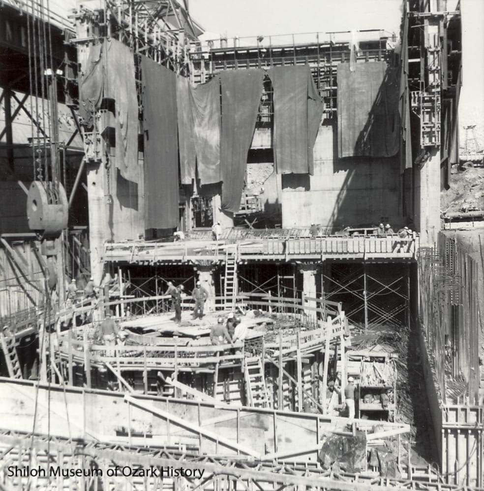
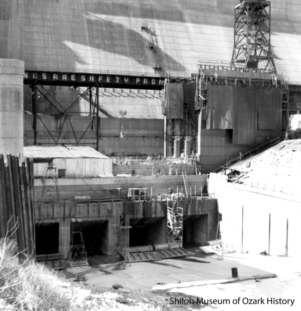
Building the turbine barrel in the powerhouse, February 1964. Thomas E. Petermann Collection (S-2005-89-140)
Not only were the T. L. James and J. A. Jones construction companies awarded the contract for the construction of the dam, they were asked to take on the powerhouse and switchyard project as well, after the company that originally won the bid was disqualified.
Although the James and Jones companies came to the project late, the milestone dates—dates by which certain portions of the project had to be completed—weren’t adjusted to reflect the delay. The contractor scrambled to begin the project in April 1963, finishing it one year later.
It helped that the contractor was using the critical path method (CPM), a newly developed system for scheduling a variety of activities in the least amount of time. Today such work is done by computer; in the early 1960s the monthly CPM chart was created manually.

One of two turbines, May 1964. Thomas E. Petermann Collection (S-2005-89-155)
To generate electricity, an intake gate on the lake side of the dam is opened. Water flows into the penstock, a long tube that travels downward and ends in a spiral scroll case. The mass of the water and the acceleration it achieves by falling and circling pushes against the turbine buckets, forcing the turbine to spin. A generator connected to the turbine shaft creates electricity which is sent to transformers in the switchyard and converted to a usable voltage. The power is delivered over high-voltage lines to an electric substation.
Beaver Dam’s powerhouse contains a small, in-house generator for its own use and two large generators, each of which can produce 56,000 kilowatts of electricity, enough for 25,000 homes. The decision to generate power is made by remote radio control from Table Rock Dam. Hydroelectric power from Beaver Dam is sold through the Southwest Power Administration, an agency of the U.S. Department of Energy, to electric companies in Arkansas, Kansas, Louisiana, Missouri, Oklahoma, and Texas.
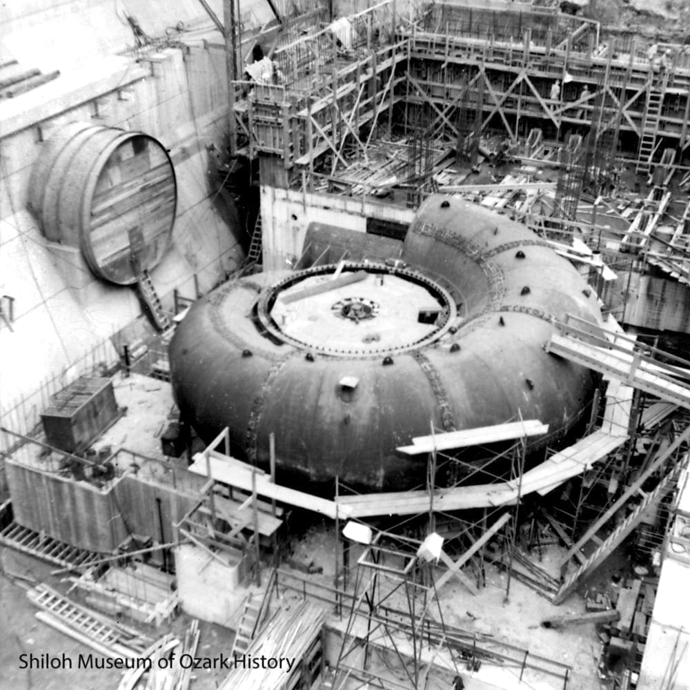
A scroll case under construction, before its connection to the penstock, Summer 1964. Thomas E. Petermann Collection (S-2005-89-141)
Under full-load conditions, the dam’s generators can produce 128 megawatts of electricity per hour (enough to supply power to a town of 100,000), although this rarely happens. Beaver Dam is a peaking plant, generating much of its power during the summer when demand is heaviest.
Once the water has spent its energy by rotating the turbines that turn the generators, it passes through the draft tube and out of the powerhouse. The concrete training walls of the tailrace guide the water into the White River. The water flows downstream to Table Rock reservoir in Missouri, where once again it is stored and used to generate electricity.
The powerhouse tailrace area, February 1964. Thomas E. Petermann Collection (S-2005-89-137)
Federal law requires that a steady flow of water moves through the dam each day to make up the flow of the White. Water may flow through the draft tube or through the hydraulic sluice gate at the base of the spillway. The released water is very cold, making it a perfect temperature for the trout stocked by the Arkansas Game and Fish Commission.
Completion

The nearly complete dam and White River, 1964. Springdale Chamber of Commerce Collection (S-85-287-6)
With the completion of the dam in March 1964 the waters of the White River began to fill the reservoir. Commercial power generation began in May 1965 and Beaver Lake was pronounced complete in June 1966. Since then millions of people have enjoyed fishing, swimming, and boating in the lake and camping along its shores.
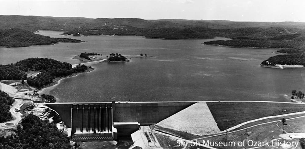
The completed dam and Beaver Lake, circa 1966. The switchyard is seen to the right of the spillway and powerhouse. Springdale News Collection (S-84-13)
What does the future hold? Growing, water-thirsty and power-hungry cities and industries are impacting the lake as do prolonged droughts. Will the lake meet our needs in the coming decades?